C2 gantry alignment
Please note: these pictures are from Robo R2 but the process and placement is the same for Robo C2.
1. Start by printing out four of these gantry alignment tools.
Note that these are not the same tools that the printer came packaged with, although those can be used as well. Also, pictured is an R the process for the C2 is exactly the same
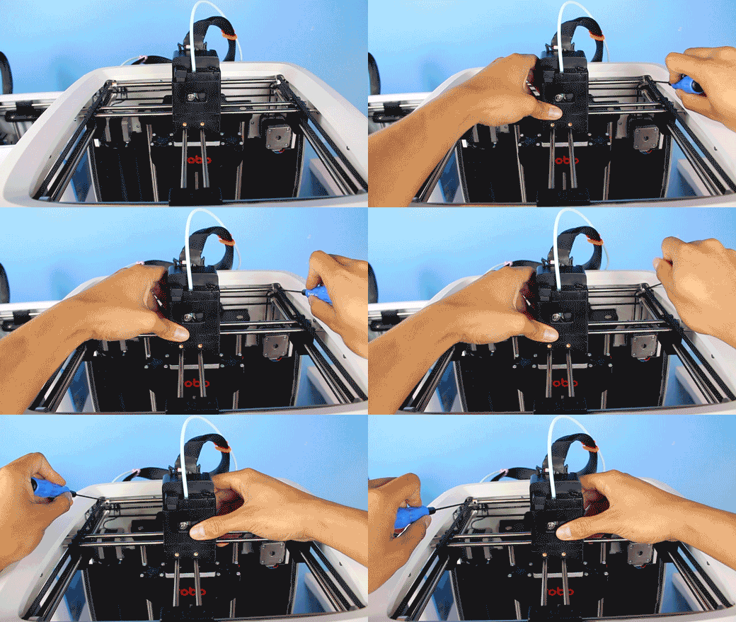
2. Start by loosening the four pulleys on the Y-axis. These four pulleys are connected to the belts which control the Y-axis motion of the machine (front to back). Do not loosen the pulleys that are connected to the motor belts.
3. Push the extruder to the back and attach the gantry alignment clips, matching them up to fit around the larger rod in the back of the gantry and the two smaller rods going across the middle. These clips will help make sure all the rods are parallel.
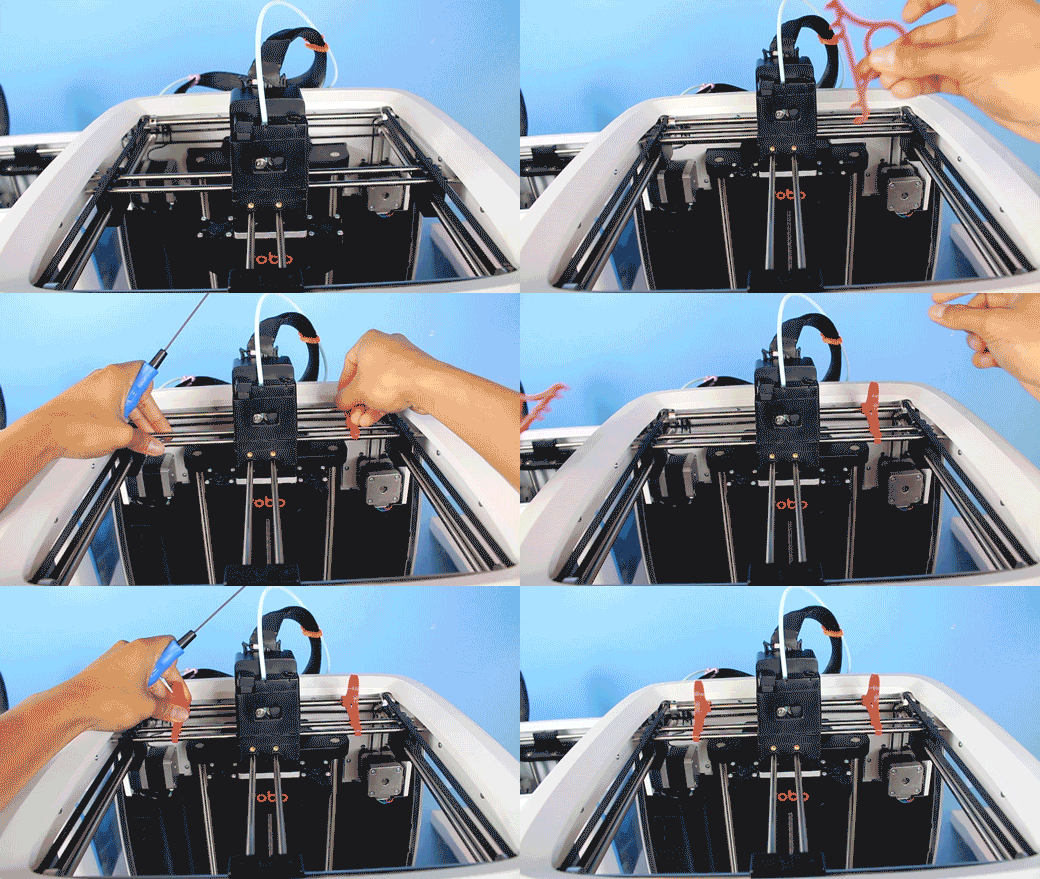
4. Push the pulleys all the way to the far ends of the rod until they bump up against the black spacers. Then tighten down the pulley set screws on all four corners of the gantry and remove the gantry clips.
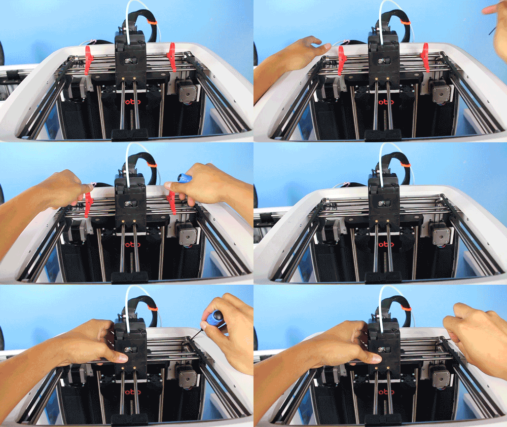
5. Now, the same needs to be done for the X-axis (side to side motion) on the left and right side of the printer. Loosen the four pulleys that are connected to the X-axis belts.
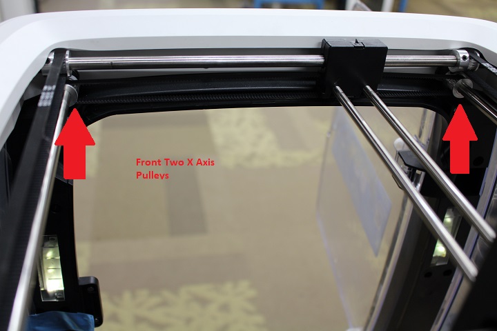
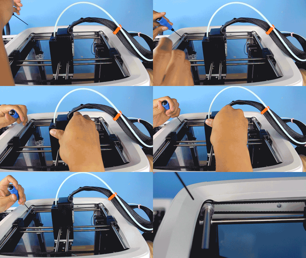
6. Doing the same as you did in steps 3 and 4, attach the gantry alignment clips, push the pulleys all the way to the far edges. Tighten the pulleys down and then take off the gantry alignment clips.
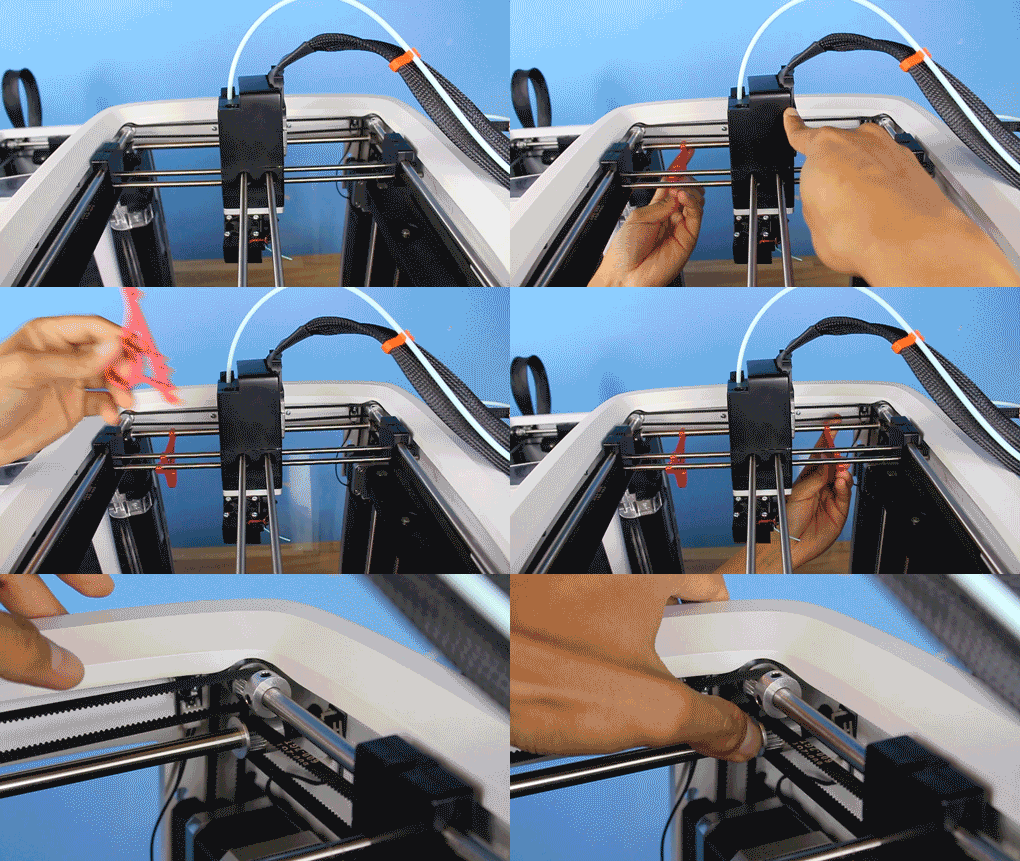
At this point you'll have adjusted pulleys in the front, back, and both sides of the gantry. You should be properly aligned and ready to go!
Happy printing!
Comments
0 comments
Please sign in to leave a comment.